The brain of the Automate-IT robot
I recently posted an article about the automate-it robotic arm. I promised to go into more detail on the brain of the Automate-IT robot so time to awake you inner geek because here is a write up about the controller hardware and software that brings the thing to life.
Controller Hardware
The hardware for the controller is an Arduino Yun microcontroller. In case you’re not familiar with Arduino according to the their website: “Arduino is an open-source electronics platform based on easy-to-use hardware and software. It’s intended for anyone making interactive projects”. There are different Arduino compatible boards available. The Yun is a special one because it combines an AVR ATmega 32u4 chip with a System on a Chip running Linux on the same board. Both are connected via a serial bus. A bridge library provides an API which enables a developers to integrate the Linux SoC into Arduino projects. The SoC part of the board provides WLAN, Ethernet, MicroSD card slot and USB Connectivity. The SoC is running an openWRT linux distribution which runs a webserver and some other services. The webserver can be manipulated from the Arduino code. This makes it very easy to build an http API on your Arduino powered device. 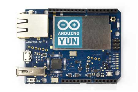 The board can provide about 50mA of power. All servo motors combined can draw up to 3Amps so I needed something a little bit more powerful. I choose the LM123K voltage regulator which gets its juice from a 12v brick type power supply. The voltage regulator magically converts it into 5v. I put the LM123K on a piece of perf board and added headers to connect the servos. Male headers on the bottom of the board turn it into a very simple Arduino shield. It doesn’t look pretty but it works fine. [caption id=“attachment_427” align=“alignnone” width=“300”]
 Voltage regulator on top of Arduino Yun[/caption]
Controller Software
The roboticArm library
The arm is programmed by recording the exact position of all the joints step by step. With each step the time it takes to execute the step is stored as well. Putting the arm to work is just a matter of playing back the recorded sequences. My roboticArm library implements this logic and presents it as a single class. The object instantiated from the class represents the robotic arm and stores a pointer to a recorded or empty sequence. The object can be in recording mode or in playback mode. When in recording mode the current position in the sequence can be selected and the positions of the servos can be set. It’s also possible to add or delete steps from the sequence. In playback mode the step number will be automatically increased when the recorded duration for a step is expired. At the end of a sequence the playback will be stopped until the step counter is reset to 0. My library uses the Arduino servo library so there is did not develop any servo control code. But since this isn’t a dedicated Arduino or development blog I won’t go into too much detail about the actual code. If you’re interested feel free to download the RoboticArm library.
Using the library
Below is an excerpt from my controller code. I did not actually test the code below and it is not very usefull since it doesn’t include any code to program a sequence. But at least the servos should come to life and go to the position configured in the defaults sequences.``` #include <Servo.h> #include <RoboticArm.h>
#define numSequences 4 #define numSequenceSteps 16
////default Sequences seqstep_t Sequences[numSequences][numSequenceSteps] = { { { 90, 90, 90, 90, 130, 25 } }, { { 90, 90, 90, 90, 130, 25 } }, { { 90, 90, 90, 90, 130, 25 } }, { { 90, 90, 90, 90, 130, 25 } } };
uint8_t sequenceSizes[numSequences] = {1, 1, 1, 1}; uint8_t selectedSequence = 0; uint8_t nextSelectedSequence = 0; //Start at 0 so arm moves to default position. File load after this bool sequenceSelected = true; //indicates if a new sequence was selected
RoboticArm myRobot;
void setup() { //serial setup; Serial.begin(9600);
//Robot setup byte ServoPins[] = {8, 9, 10, 11, 12}; myRobot.begin(ServoPins);
}
void loop() { if (sequenceSelected) { if (! myRobot.issequenceRunning()) { selectedSequence = nextSelectedSequence; myRobot.setSequence(Sequences[selectedSequence], sequenceSizes[selectedSequence]); sequenceSelected = false; } }
myRobot.go();
//delay(50); // Poll every 50ms }
### The REST API

The controller presents a REST API via the linux part of the Yun. The beauty of the Yun is that you can actually code this API in the Arduino code. Unfortunately this also means there is no framework available that makes creating a REST API easier. And even if there was I doubt it would fit in the Atmega's RAM or Flash. The first thing to tackle when creating a REST API is the routing. Routing basically means figuring out what we need to do when a certain URL is requested. You could read the request and use a huge switch case contruction to figure out where to go. but this uses up valuable program storage and ram in a microcontroller. On top of that I find it cumbersome to program in that way. So I used a slightly different approach. I use a URL structure that looks like this: http://RESThost/category/command/parameter. Based on that I wrote the code below:```
typedef void (\* FuncPtr) (YunClient);

static char restCategories\[3\]\[9\] = { "status", "record", "sequence" };
static char restCommands\[3\]\[5\]\[9\] = {
  { "record", "servo", "step", "sequence", "steptime" },
  { "on", "off", "servo", "steptime", "delstep" },
  { "set", "step", "numsteps", "load", "save" }
};

static FuncPtr restFunctions\[\]\[5\] = {
  { statusRecordCommand, statusServoCommand, statusStepCommand, statusSequenceCommand, statusStepTimeCommand },
  { recordOnCommand, recordOffCommand, setServoCommand, setStepTimeCommand, delStepCommand },
  { setSequenceCommand, setStepCommand, getNumStepsCommand, loadSequenceCommand, saveSequenceCommand }
};
```To figure out which function to run my code uses 3 arrays. The first is an array of strings (or technically a two dimensional array of characters) which defines the categories we have. The second array is a three dimensional array of characters which defines the commands available for each category. The last array is a two dimensional array of function pointers. When a request comes in the code looks for the corresponding element in the first array. Then it know the index number of the category so it starts looking for the element matching the command in the second array. When the command is found the code knows both the index number for the category and the command and uses these index number to find the pointer to the right function in the third array and runs the function. If the function need any parameters the rest of the URL is read and used as parameter. For example: http://roboticarm/status/record will start the function statusRecordCommand() which toggles the recording mode flag of the roboticArm object.

### Putting it all together

I made the whole project available for download. You can find it here: [robotic\_arm](http://automate-it.today/wp-content/uploads/2014/08/robotic_arm.tar.gz). Don't forget to also download the [RoboticArm library](http://automate-it.today/wp-content/uploads/2014/08/RoboticArm-lib.tar.gz) and put it somewhere the arduini IDE can find it. The download also includes the AJAX Gui to program the arm. This was my first time building such a gui so it doesn't like very nice and the code can probably be optimized. So feel free to modify the code and send me the results :). Disclaimer: The code was only tested on Arduino Yun. The library will run fine on any other Arduino as long as you configure the correct pin numbers. The REST API and Ajax Gui will not work on any other Arduino board currently available.